Basic Theory of Frequency Response Function
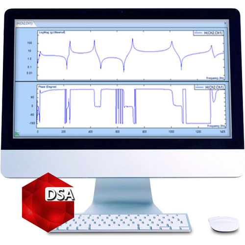
A common application of dynamic signal analyzers is the measurement of the Frequency Response Function (FRF) of mechanical systems. This is also known as Network Analysis, where both system inputs and outputs are measured simultaneously. With these multi-channel measurements, the analyzer can measure how the system “changes” the inputs. If the system is linear, which is a common assumption, then this “change” is fully described by the Frequency Response Function (FRF). In fact, for a linear and stable system, the response of the system to any input can be predicted just by knowing the Frequency Response Function.
Broadband random, sine, step or transient signals are widely used as excitation signals in test and measurement applications. Figure 1 illustrates that an excitation signal x, can be applied to a UUT (Unit Under Test) and generate one or multiple responses denoted by y. The relationship between the input and output is known as the transfer function or frequency response function and represented by H(y,x). In general a transfer function is a complex function that describes how the system modifies the input signal magnitude and phase as a function of the excitation frequency.
Functions : frequency response function measurement
Applications : multichannel analyzer
Type : real-time, 2D




Reviews
There are no reviews yet.